
Page 372 - Planning and Design of Airports
P. 372
324 Airp o r t D e sign
45° 45°
3
0.9
MIDPOINT OF 100 30
RUNWAY
100 30
5
MAX.
1.5
100 30
5
MAX.
1.5
100 30
45° 45°
50 15
5
MAX. RUNWAY THRESHOLD
1.5
DIMENSIONS ARE
EXPRESSED THUS:
FEET e.g., 10
METERS 3
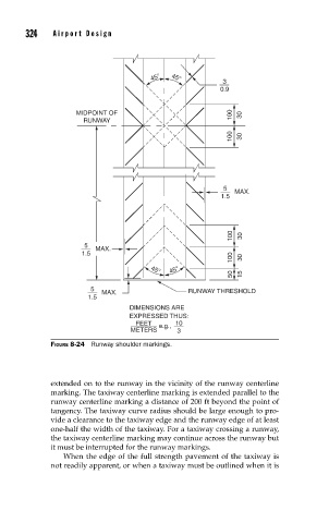
FIGURE 8-24 Runway shoulder markings.
extended on to the runway in the vicinity of the runway centerline
marking. The taxiway centerline marking is extended parallel to the
runway centerline marking a distance of 200 ft beyond the point of
tangency. The taxiway curve radius should be large enough to pro-
vide a clearance to the taxiway edge and the runway edge of at least
one-half the width of the taxiway. For a taxiway crossing a runway,
the taxiway centerline marking may continue across the runway but
it must be interrupted for the runway markings.
When the edge of the full strength pavement of the taxiway is
not readily apparent, or when a taxiway must be outlined when it is