
Page 374 - Planning and Design of Airports
P. 374
326 Airp o r t D e sign
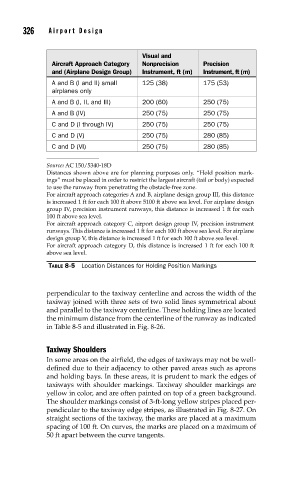
Visual and
Aircraft Approach Category Nonprecision Precision
and (Airplane Design Group) Instrument, ft (m) Instrument, ft (m)
A and B (I and II) small 125 (38) 175 (53)
airplanes only
A and B (I, II, and III) 200 (60) 250 (75)
A and B (IV) 250 (75) 250 (75)
C and D (I through IV) 250 (75) 250 (75)
C and D (V) 250 (75) 280 (85)
C and D (VI) 250 (75) 280 (85)
Source: AC 150/5340-18D
Distances shown above are for planning purposes only. “Hold position mark-
ings” must be placed in order to restrict the largest aircraft (tail or body) expected
to use the runway from penetrating the obstacle-free zone.
For aircraft approach categories A and B, airplane design group III, this distance
is increased 1 ft for each 100 ft above 5100 ft above sea level. For airplane design
group IV, precision instrument runways, this distance is increased 1 ft for each
100 ft above sea level.
For aircraft approach category C, airport design group IV, precision instrument
runways. This distance is increased 1 ft for each 100 ft above sea level. For airplane
design group V, this distance is increased 1 ft for each 100 ft above sea level.
For aircraft approach category D, this distance is increased 1 ft for each 100 ft
above sea level.
TABLE 8-5 Location Distances for Holding Position Markings
perpendicular to the taxiway centerline and across the width of the
taxiway joined with three sets of two solid lines symmetrical about
and parallel to the taxiway centerline. These holding lines are located
the minimum distance from the centerline of the runway as indicated
in Table 8-5 and illustrated in Fig. 8-26.
Taxiway Shoulders
In some areas on the airfield, the edges of taxiways may not be well-
defined due to their adjacency to other paved areas such as aprons
and holding bays. In these areas, it is prudent to mark the edges of
taxiways with shoulder markings. Taxiway shoulder markings are
yellow in color, and are often painted on top of a green background.
The shoulder markings consist of 3-ft-long yellow stripes placed per-
pendicular to the taxiway edge stripes, as illustrated in Fig. 8-27. On
straight sections of the taxiway, the marks are placed at a maximum
spacing of 100 ft. On curves, the marks are placed on a maximum of
50 ft apart between the curve tangents.