
Page 370 - Planning and Design of Airports
P. 370
322 Airp o r t D e sign
NOTES
1. RUNWAY SIDE STRIPES, WHEN USED ON THE RUNWAY,
EXTEND INTO THE DISPLACED AREA. SEE FIGURE 11, DETAIL ‘A’
2. RUNWAY MARKINGS (EXCEPT HOLDING POSITION
MARKINGS), INCLUDING THOSE IN THE DISPLACED
THRESHOLD AREA, ARE WHITE. 80 120 100 STANDARD RUNWAY
FEET 10 24 36 30 20 MARKING
3. DIMENSIONS EXPRESSED AS e.g.,
METERS 3 6
RUNWAY SIDE >
STRIPES (WHITE) SEE DETAIL ‘A’ FOR
ARROW DIMENSIONS >
> > >
TAXIWAY >
CENTERLINE 200 RUNWAY THRESHOLD IS AT
MARKINGS 60 OUTBOARD EDGE OF >
(YELLOW) THRESHOLD BAR
45 5
SEE DETAIL ‘A’ 1.5 THRESHOLD
13.5 10
5 AND TABLE BELOW BAR (WHITE)
1.5 W- RUNWAY WIDTH 3
TAIL 1.5
5
15
4.5 HEAD RUNWAY # OF ARROW SPACING BETWEEN SPACING TO
3
WIDTH HEADS ARROW HEADS RUNWAY EDGE
1
20 ≥ 100' (30 M) 4 W/4 W/8
24 TAXIWAY
EDGE < 100' (30 M) 3 W/3 W/6
DETAIL ‘A’ (ARROW) STRIPES < 60' (30 M) 2 W/2 W/4
(YELLOW)
NOTE: ‘W’ IS THE RUNWAY WIDTH
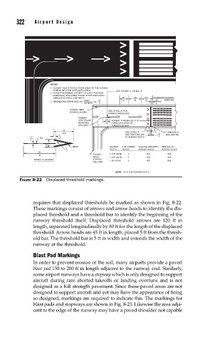
FIGURE 8-22 Displaced threshold markings.
requires that displaced thresholds be marked as shown in Fig. 8-22.
These markings consist of arrows and arrow heads to identify the dis-
placed threshold and a threshold bar to identify the beginning of the
runway threshold itself. Displaced threshold arrows are 120 ft in
length, separated longitudinally by 80 ft for the length of the displaced
threshold. Arrow heads are 45 ft in length, placed 5 ft from the thresh-
old bar. The threshold bar is 5 ft in width and extends the width of the
runway at the threshold.
Blast Pad Markings
In order to prevent erosion of the soil, many airports provide a paved
blast pad 150 to 200 ft in length adjacent to the runway end. Similarly,
some airport runways have a stopway which is only designed to support
aircraft during rare aborted takeoffs or landing overruns and is not
designed as a full strength pavement. Since these paved areas are not
designed to support aircraft and yet may have the appearance of being
so designed, markings are required to indicate this. The markings for
blast pads and stopways are shown in Fig. 8-23. Likewise the area adja-
cent to the edge of the runway may have a paved shoulder not capable