
Page 373 - Planning and Design of Airports
P. 373
Airport Lighting, Marking, and Signage 325
15
SEE SEE SEE DETAIL ‘A’ TAXIWAY/RUNWAY
TABLE 4 TABLE 4 HOLDING POSITION
MARKINGS*
ILS HOLDING POSITION
MARKINGS*
REQUIRED DISTANCE
3' (1 m)
FROM RUNWAY
CENTERLINE
NOTE THAT HOLDLINE DETAIL ‘A’ TAXIWAY EDGE
MARKINGS,
WOULD INFRINGE ON
PARALLEL TAXIWAY IF 3’ DIMENSION IS DASHED *
NOT REORIENTED EDGE TO EDGE TAXIWAY EDGE
MARKINGS,
CONTINUOUS *
INTERMEDIATE HOLDING HOLDING BAY
POSITION MARKINGS*
EXAMPLE OF HOLDING POSITION MARKINGS NOT AT
RIGHT ANGLE TO TAXIWAY CENTERLINE BECAUSE OF * REFER TO FIGURE TO
FOR MARKING DETAILS
INTERSECTION CONFIGURATION
RUNWAY RUNWAY
SEE AC 150/5340–18 POFZ MARKINGS
FOR SIGN REQUIREMENTS
AT HOLDING POSITION MARKINGS
HOLDING
BAY
TAXIWAY TAXIWAY
EXAMPLE WHERE HOLDING POSITION MARKINGS EXAMPLE OF HOLDING POSITION MARKINGS
DO NOT EXTEND STRAIGHT ACROSS THE TAXIWAY EXTENDED ACROSS HOLDING BAY
NOTE: FOR CAT II & III APPROACHES
MAINTAIN A CLEAR SECTION
200‘x1000’ AT RUNWAY END.
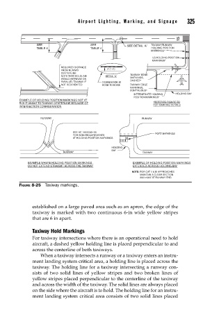
FIGURE 8-25 Taxiway markings.
established on a large paved area such as an apron, the edge of the
taxiway is marked with two continuous 6-in wide yellow stripes
that are 6 in apart.
Taxiway Hold Markings
For taxiway intersections where there is an operational need to hold
aircraft, a dashed yellow holding line is placed perpendicular to and
across the centerline of both taxiways.
When a taxiway intersects a runway or a taxiway enters an instru-
ment landing system critical area, a holding line is placed across the
taxiway. The holding line for a taxiway intersecting a runway con-
sists of two solid lines of yellow stripes and two broken lines of
yellow stripes placed perpendicular to the centerline of the taxiway
and across the width of the taxiway. The solid lines are always placed
on the side where the aircraft is to hold. The holding line for an instru-
ment landing system critical area consists of two solid lines placed