
Page 100 - Plastics Engineering
P. 100
Mechanical Behaviour of Plastics 83
The obvious question is ‘Is there an optimum design for the corrugations?’
Unforhmately the answer is ‘No’ because if one wishes to increase transverse
stiffness then the obvious thing to do is to increase D up to the point where
buckling problems start to be a concern. Usually this is when D/h = 10, for
short-term loading and less than this for long term loading because of the
decrease in modulus of viscoelastic materials.
Another approach is to recognise that initially for a flat sheet, the axial
stiffness is high but the transverse stiffness is relatively low. As the corrugation
depth increases then the transverse stiffness increases but at the expense of the
axial stiffness. It is readily shown that the axial deflection per unit load for the
corrugations for the new geometry compared with the flat sheet is given by
4n3h
Axial stiffness ratio = - (2.26)
L sin2 a
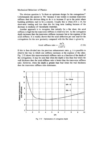
If this is then divided into the previous enhancement ratio, q, it is possible to
observe the way in which one stiffness increases at the expense of the other.
Fig. 2.32 shows this transverse/axial stiffness ratio as a function of the depth of
the corrugations. It may be seen that when the depth is less than four times the
wall thickness then the axial stiffness ratio is better than the transverse stiffness
ratio. However, when the depth is greater than four times the wall thickness
then the transverse stiffness ratio dominates.
14
12
3 lo
t
E=
--E
6
4
2
0
1 2 3 4 5 6 7 a 9 10
Dh
Fig. 2.32 Optimisation of Corrugation depth