
Page 96 - Plastics Engineering
P. 96
Mechanical Behaviour of Plastics 79
ribbed section which would meet this requirement. One practical consideration
is that the thickness of the rib should be less than the thickness of the top plate
(d) in order that there will be no evidence (sink mark) to show the presence
of the rib on the underside of the plate. A typical ratio (#?) of rib thickness to
plate thickness is 0.6.
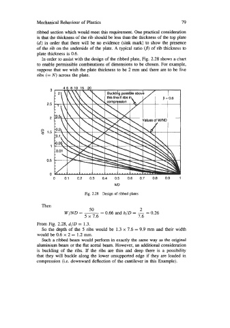
In order to assist with the design of the ribbed plate, Fig. 2.28 shows a chart
to enable permissible combinations of dimensions to be chosen. For example,
suppose that we wish the plate thickness to be 2 mm and there are to be five
ribs (= N) across the plate.
3
2.5
2
n
a 1.5
1
0.5
0
0 0.1 0.2 0.3 0.4 0.5 0.6 0.7 0.8 0.9 1
h/D
Fig. 2.28 Design of ribbed plates
Then
50
WIND = - 2
= 0.66 and h/D = - = 0.26
5 x 7.6 7.6
From Fig. 2.28, d/D = 1.3.
So the depth of the 5 ribs would be 1.3 x 7.6 = 9.9 mm and their width
would be 0.6 x 2 = 1.2 m.
Such a ribbed beam would perform in exactly the same way as the original
aluminium beam or the flat acetal beam. However, an additional consideration
is buckling of the ribs. If the ribs are thin and deep there is a possibility
that they will buckle along the lower unsupported edge if they are loaded in
compression (Le. downward deflection of the cantilever in this Example).