
Page 274 - Plastics Engineering
P. 274
Processing of Plastics 257
2.5E-005
2E-005
1 E405
0
0 10 20 30 40 50 60 70 80 90
Screw flight angle
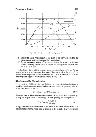
Fig. 4.10 Variation of drag flow and pressure flow
(i) this is the angle which occurs if the pitch of the screw is equal to the
diameter and so it is convenient to manufacture,
(ii) for a considerable portion of the extruder length, the screw is acting as a
solids conveying device and it is known that the optimum angle in such
cases is 17" to 20".
It should also be noted that in some cases correction factors, Fd, and Fp are
applied to the drag and pressure flow terms. They are to allow for edge effects
and are solely dependent on the channel width, T, and channel depth, h, in the
metering zone. Qpical values are illustrated in Fig. 4.11.
4.2.4 Extruderme Characteristics
From equation (4.9) it may be seen that there are two interesting situations to
consider. One is the case of free discharge where there is no pressure build up
at the end of the extruder so
=
Q = emax ;X~D*NH sin4cos4 (4.10)
The other case is where the pressure at the end of the extruder is large enough
to stop the output. From (4.9) with Q = 0 and ignoring the leakage flow
6rDLNq
P=P,,= (4.11)
H2tan4
In Fig. 4.12 these points are shown as the limits of the screw characteristic. It is
interesting to note that when a die is coupled to the extruder their requirements