
Page 269 - Plastics Engineering
P. 269
252 Processing of Plastics
adiabatic. This means that the system is fully insulated to prevent heat gain
or loss from or to the surroundings. If this ideal state was to be reached in the
extruder it would be necessary for the work done on the melt to produce just
the right amount of heat without the need for heating or cooling. The second
ideal case is referred to as isothermal. In the extruder this would mean that the
temperature at all points is the same and would require immediate heating or
cooling from the barrel to compensate for any loss or gain of heat in the melt.
In practice the thermal processes in the extruder fall somewhere between these
ideals. Extruders may be run without external heating or cooling but they are
not truly adiabatic since heat losses will occur. Isothermal operation along the
whole length of the extruder cannot be envisaged if it is to be supplied with
relatively cold granules. However, particular sections may be near isothermal
and the metering zone is often considered as such for analysis.
4.2.3 Analysis of Flow in Extruder
As discussed in the previous section, it is convenient to consider the output
from the extruder as consisting of three components - drag flow, pressure flow
and leakage. The derivation of the equation for output assumes that in the
metering zone the melt has a constant viscosity and its flow is isothermal in
a wide shallow channel. These conditions are most likely to be approached in
the metering zone.
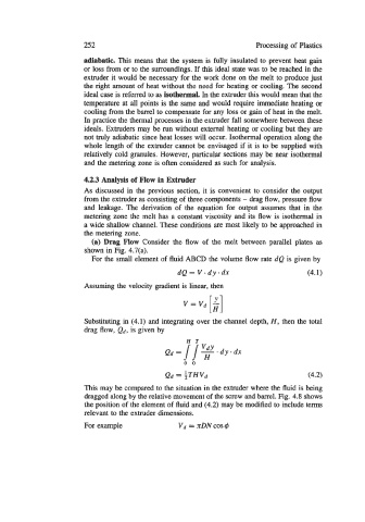
(a) Drag Flow Consider the flow of the melt between parallel plates as
shown in Fig. 4.7(a).
For the small element of fluid ABCD the volume flow rate dQ is given by
dQ= V*dy*dx (4.1)
Assuming the velocity gradient is linear, then
Substituting in (4.1) and integrating over the channel depth, H, then the total
drag flow, Qd, is given by
This may be compared to the situation in the extruder where the fluid is being
dragged along by the relative movement of the screw and barrel. Fig. 4.8 shows
the position of the element of fluid and (4.2) may be modified to include terms
relevant to the extruder dimensions.
For example vd = RDN cos $