
Page 121 - Power Electronic Control in Electrical Systems
P. 121
//SYS21/F:/PEC/REVISES_10-11-01/075065126-CH004.3D ± 109 ± [106±152/47] 17.11.2001 9:54AM
Power electronic control in electrical systems 109
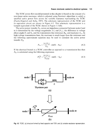
The TCSC power flow model presented in this chapter is based on the concept of a
non-linear series reactance, which is adjusted using Newton's algorithm to satisfy a
specified active power flow across the variable reactance representing the TCSC
(Fuerte-Esquivel and Acha, 1997). The schematic representation of the TCSC and
its equivalent circuit are shown in Figure 4.2. This schematic representation is a
lumped equivalent of the TCSC shown in Figure 1.11(b).
The active power transfer P lm across an impedance connected between nodes l and
m is determined by the voltage magnitudes jV l j and jV m j, the difference in voltage
phase angles y l and y m and the transmission line resistance R lm and reactance X lm .In
high-voltage transmission lines, the reactance is much larger than the resistance and
the following approximate equation may be used to calculate the active power
transfer P lm
jV l kV m j
P lm sin(y l y m ) (4:2)
X lm
If the electrical branch is a TCSC controller as opposed to a transmission line then
P lm is calculated using the following expression
reg
P lm jV l kV m j sin(y l y m ) (4:3)
X TCSC
Fig. 4.2 TCSC. (a) structure formed by fixed capacitor and TCR; and (b) variable reactance representation.