
Page 116 - Power Electronic Control in Electrical Systems
P. 116
//SYS21/F:/PEC/REVISES_10-11-01/075065126-CH003.3D ± 104 ± [82±105/24] 17.11.2001 9:53AM
104 Transmission system compensation
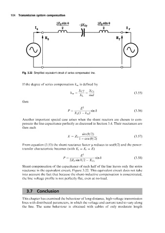
Fig. 3.22 Simplified equivalent circuit of series compensated line.
If the degree of series compensation k se is defined by
X C g X Cg
k se (3:55)
X L oal
then
E 2
P sin d (3:56)
X L (1 k se )
Another important special case arises when the shunt reactors are chosen to com-
pensate the line capacitance perfectly as discussed in Section 3.4. Their reactances are
then each
sin (y=2)
X Z 0 (3:57)
1 cos (y=2)
From equation (3.53) the shunt reactance factor m reduces to sec(y/2) and the power-
transfer characteristic becomes (with E s E r E)
E 2
P sin d (3:58)
2Z 0 sin y=2 X Cg
Shunt compensation of the capacitance of each half of the line leaves only the series
reactance in the equivalent circuit, Figure 3.22. This equivalent circuit does not take
into account the fact that because the shunt-inductive compensation is concentrated,
the line voltage profile is not perfectly flat, even at no-load.
3.7 Conclusion
This chapter has examined the behaviour of long-distance, high-voltage transmission
lines with distributed parameters, in which the voltage and current tend to vary along
the line. The same behaviour is obtained with cables of only moderate length