
Page 113 - Power Electronic Control in Electrical Systems
P. 113
//SYS21/F:/PEC/REVISES_10-11-01/075065126-CH003.3D ± 101 ± [82±105/24] 17.11.2001 9:53AM
Power electronic control in electrical systems 101
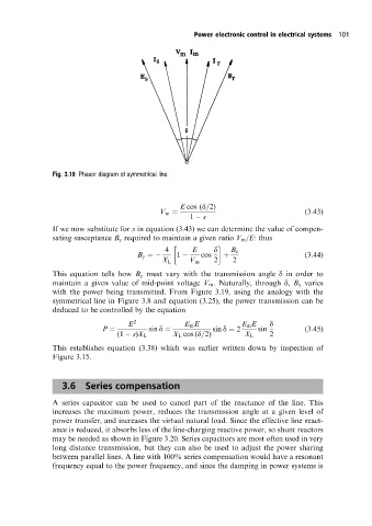
Fig. 3.19 Phasor diagram of symmetrical line.
E cos (d=2)
V m (3:43)
1 s
If we now substitute for s in equation (3.43) we can determine the value of compen-
sating susceptance B g required to maintain a given ratio V m /E: thus
4 E d B c
B g 1 cos (3:44)
X L V m 2 2
This equation tells how B g must vary with the transmission angle d in order to
maintain a given value of mid-point voltage V m . Naturally, through d, B g varies
with the power being transmitted. From Figure 3.19, using the analogy with the
symmetrical line in Figure 3.8 and equation (3.25), the power transmission can be
deduced to be controlled by the equation
E 2 E m E E m E d
P sin d sin d 2 sin (3:45)
(1 s)X L X L cos (d=2) X L 2
This establishes equation (3.38) which was earlier written down by inspection of
Figure 3.15.
3.6 Series compensation
A series capacitor can be used to cancel part of the reactance of the line. This
increases the maximum power, reduces the transmission angle at a given level of
power transfer, and increases the virtual natural load. Since the effective line react-
ance is reduced, it absorbs less of the line-charging reactive power, so shunt reactors
may be needed as shown in Figure 3.20. Series capacitors are most often used in very
long distance transmission, but they can also be used to adjust the power sharing
between parallel lines. A line with 100% series compensation would have a resonant
frequency equal to the power frequency, and since the damping in power systems is