
Page 108 - Power Electronic Control in Electrical Systems
P. 108
//SYS21/F:/PEC/REVISES_10-11-01/075065126-CH003.3D ± 96 ± [82±105/24] 17.11.2001 9:53AM
96 Transmission system compensation
Fig. 3.11 Shunt reactors distributed along a high-voltage AC line.
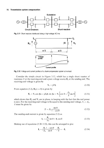
Fig. 3.12 Voltage and current profiles of a shunt-compensated system at no-load.
Consider the simple circuit in Figure 3.12, which has a single shunt reactor of
reactance X at the receiving end and a pure voltage source E s at the sending end. The
receiving-end voltage is given by
V r jXI r (3:30)
From equation (3.2), E s (x 0) is given by
Z 0
E s V r cos ba jZ 0 I r sin ba V r cos y sin y (3:31)
X
which shows that E s and V r are in phase, in keeping with the fact that the real power
is zero. For the receiving-end voltage to be equal to the sending-end voltage, V r E s ,
X must be given by
sin y
X Z 0 (3:32)
1 cos y
The sending-end current is given by equation (3.2) as
E s
I s j sin y I r cos y (3:33)
Z 0
Making use of equations (3.30±3.32), this can be arranged to give
E s 1 cos y E s
I s j j I r (3:34)
Z 0 sin y X