Page 105 - Power Electronic Control in Electrical Systems
P. 105

//SYS21/F:/PEC/REVISES_10-11-01/075065126-CH003.3D ± 93 ± [82±105/24] 17.11.2001 9:53AM


                                                             Power electronic control in electrical systems 93

                      A more familiar form of this equation is obtained for short lines, for which
                                       p                    p      p
                      sin y ' y ˆ ba ˆ oa (lc). Then Z 0 y ˆ oa (lc)    (l/c) ˆ oal ˆ X L , the series
                      inductive reactance of the line. So
                                                        E s E r
                                                    P ˆ     sin d                        (3:25)
                                                         X L
                      This equation is important because of its simplicity and wide-ranging validity. If E s and
                      E r are held constant (as is normally the case), the power transmission is a function of
                      only one variable, d. As noted earlier, there is a maximum transmissible power,

                                                        E s E r  P 0
                                                 P max ˆ    ˆ                            (3:26)
                                                         X L   sin y
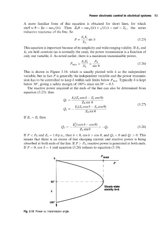
                      This is shown in Figure 3.10, which is usually plotted with d as the independent
                      variable; but in fact P is generally the independent variable and the power transmis-
                      sion has to be controlled to keep d within safe limits below P max . Typically d is kept
                      below 30 , giving a safety margin of 100% since sin 30 ˆ 0:5:


                        The reactive power required at the ends of the line can also be determined from
                      equation (3.23): thus
                                                  E r (E s cos d   E r cos y)
                                             Q r ˆ
                                                        Z 0 sin y                        (3:27)
                                                    E s (E r cos d   E s cos y)
                                             Q s ˆ
                                                          Z 0 sin y
                      If E s ˆ E r then
                                                    2
                                                   E (cos d   cos y)
                                                    s
                                            Q s ˆ                 ˆ Q r                  (3:28)
                                                       Z 0 sin y
                      If P < P 0 and E s ˆ 1:0p:u:, then d < y, cos d > cos y, and Q s < 0and Q r > 0. This
                      means that there is an excess of line charging current and reactive power is being
                      absorbed at both ends of the line. If P > P 0 , reactive power is generated at both ends.
                      If P ˆ 0, cos d ˆ 1 and equation (3.28) reduces to equation (3.19).


                      Fig. 3.10 Power vs. transmission angle.
   100   101   102   103   104   105   106   107   108   109   110