
Page 100 - Power Electronic Control in Electrical Systems
P. 100
//SYS21/F:/PEC/REVISES_10-11-01/075065126-CH003.3D ± 88 ± [82±105/24] 17.11.2001 9:53AM
88 Transmission system compensation
Fig. 3.4 Phasor diagram of uncompensated line on open-circuit.
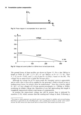
Fig. 3.5 Voltage and current profiles for a 300-km line at no load (open-circuit).
The general forms of these profiles are shown in Figure 3.5. For a line 300 km in
5
length at 50 Hz, b 360 f /3 10 6 per 100 km, so y 6 3 18 . Then
V r E s / cos y 1:05E s and I s (E s /Z 0 ) tan y 0:329 p:u: based on the SIL. The
voltage rise on open-circuit is called the Ferranti effect.
Although the voltage rise of 5% seems small, the `charging' current is appreciable
and in such a line it must all be supplied by the generator, which is forced to run at
1
leading power factor, for which it must be underexcited. Note that a line for which
y ba p/2 has a length of l/4 (one quarter-wavelength, i.e. 1500 km at 50 Hz),
producing an infinite voltage rise. Operation of any line approaching this length is
completely impractical without some means of compensation.
In practice the open-circuit voltage rise will be greater than is indicated by
equation (3.10), which assumes that the sending-end voltage is fixed. Following a
1
The extent to which generators can absorb reactive power is limited by stability and core-end heating.
Operation of generators in the absorbing mode, with a leading power factor, is called `under-excited'
because the field current and open-circuit emf are reduced below their normal rated-load values.