Page 97 - Power Electronic Control in Electrical Systems
P. 97

//SYS21/F:/PEC/REVISES_10-11-01/075065126-CH003.3D ± 85 ± [82±105/24] 17.11.2001 9:53AM


                                                             Power electronic control in electrical systems 85

                      Table 3.2 Advantages and disadvantages of different types of compensating equipment for transmission
                      systems
                      Compensating equipment  Advantages            Disadvantages

                      Switched shunt reactor  Simple                Fixed value
                      Switched shunt capacitor  Simple              Fixed value
                                                                    Switching transients
                      Series capacitor       Simple                 Requires over-voltage protection and
                                                                    subharmonic filters
                                                                    Limited overload capability
                      Synchronous condenser  Has useful overload capability  High maintenance requirement
                                             Fully controllable     Slow response
                                             Low harmonics          Heavy
                      Polyphase-saturated    Rugged construction    Fixed value
                      reactor (TCR)          Large overload capability  Noisy
                                             Low harmonics
                      Thyristor-controlled reactor  Fast response   Requires shunt capacitors/filters
                      (TCR)                  Fully controllable     Generates harmonics
                                             No effect on fault level
                      Thyristor-switched capacitor  No harmonics    No inherent absorbing capability
                      (TSC)                                         to limit over-voltages
                                                                    Complex buswork
                                                                    Low frequency resonances
                                                                    with system


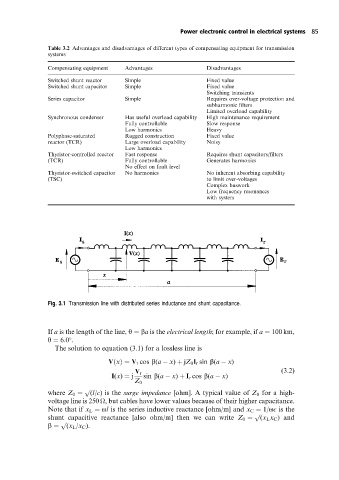
                      Fig. 3.1 Transmission line with distributed series inductance and shunt capacitance.


                      If a is the length of the line, y ˆ ba is the electrical length; for example, if a ˆ 100 km,
                      y ˆ 6:0 .

                        The solution to equation (3.1) for a lossless line is
                                        V…x†ˆ V r cos b(a   x) ‡ jZ 0 I r sin b(a   x)
                                                                                          (3:2)
                                               V r
                                         I(x) ˆ j  sin b(a   x) ‡ I r cos b(a   x)
                                               Z 0
                                 p
                      where Z 0 ˆ  (l/c) is the surge impedance [ohm]. A typical value of Z 0 for a high-
                      voltage line is 250 
, but cables have lower values because of their higher capacitance.
                      Note that if x L ˆ ol is the series inductive reactance [ohm/m] and x C ˆ 1/oc is the
                                                                                  p
                      shunt capacitive reactance [also ohm/m] then we can write Z 0 ˆ  (x L x C )and
                          p
                      b ˆ   (x L /x C ).
   92   93   94   95   96   97   98   99   100   101   102