
Page 102 - Power Electronic Control in Electrical Systems
P. 102
//SYS21/F:/PEC/REVISES_10-11-01/075065126-CH003.3D ± 90 ± [82±105/24] 17.11.2001 9:53AM
90 Transmission system compensation
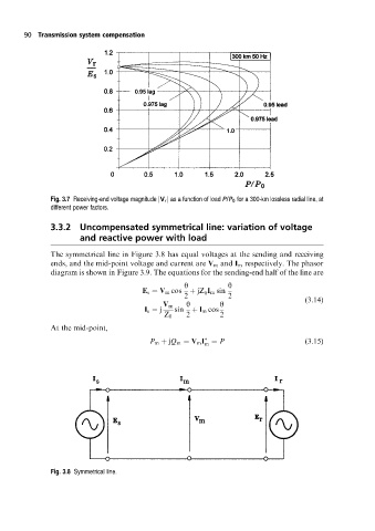
Fig. 3.7 Receiving-end voltage magnitude jV r j as a function of load P/P 0 for a 300-km lossless radial line, at
different power factors.
3.3.2 Uncompensated symmetrical line: variation of voltage
and reactive power with load
The symmetrical line in Figure 3.8 has equal voltages at the sending and receiving
ends, and the mid-point voltage and current are V m and I m respectively. The phasor
diagram is shown in Figure 3.9. The equations for the sending-end half of the line are
y y
E s V m cos jZ I m sin
0
2 2 (3:14)
V m y y
I s j sin I m cos
Z 0 2 2
At the mid-point,
P m jQ m V m I P (3:15)
m
Fig. 3.8 Symmetrical line.