
Page 107 - Power Electronic Control in Electrical Systems
P. 107
//SYS21/F:/PEC/REVISES_10-11-01/075065126-CH003.3D ± 95 ± [82±105/24] 17.11.2001 9:53AM
Power electronic control in electrical systems 95
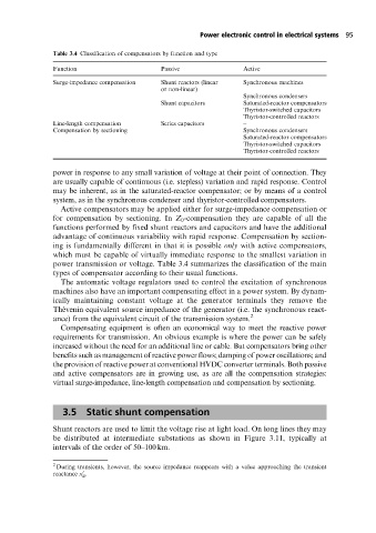
Table 3.4 Classification of compensators by function and type
Function Passive Active
Surge-impedance compensation Shunt reactors (linear Synchronous machines
or non-linear)
Synchronous condensers
Shunt capacitors Saturated-reactor compensators
Thyristor-switched capacitors
Thyristor-controlled reactors
Line-length compensation Series capacitors ±
Compensation by sectioning ± Synchronous condensers
Saturated-reactor compensators
Thyristor-switched capacitors
Thyristor-controlled reactors
power in response to any small variation of voltage at their point of connection. They
are usually capable of continuous (i.e. stepless) variation and rapid response. Control
may be inherent, as in the saturated-reactor compensator; or by means of a control
system, as in the synchronous condenser and thyristor-controlled compensators.
Active compensators may be applied either for surge-impedance compensation or
for compensation by sectioning. In Z 0 -compensation they are capable of all the
functions performed by fixed shunt reactors and capacitors and have the additional
advantage of continuous variability with rapid response. Compensation by section-
ing is fundamentally different in that it is possible only with active compensators,
which must be capable of virtually immediate response to the smallest variation in
power transmission or voltage. Table 3.4 summarizes the classification of the main
types of compensator according to their usual functions.
The automatic voltage regulators used to control the excitation of synchronous
machines also have an important compensating effect in a power system. By dynam-
ically maintaining constant voltage at the generator terminals they remove the
The  venin equivalent source impedance of the generator (i.e. the synchronous react-
ance) from the equivalent circuit of the transmission system. 2
Compensating equipment is often an economical way to meet the reactive power
requirements for transmission. An obvious example is where the power can be safely
increased without the need for an additional line or cable. But compensators bring other
benefits such as management of reactive power flows; damping of power oscillations; and
the provision of reactive power at conventional HVDC converter terminals. Both passive
and active compensators are in growing use, as are all the compensation strategies:
virtual surge-impedance, line-length compensation and compensation by sectioning.
3.5 Static shunt compensation
Shunt reactors are used to limit the voltage rise at light load. On long lines they may
be distributed at intermediate substations as shown in Figure 3.11, typically at
intervals of the order of 50±100 km.
2
During transients, however, the source impedance reappears with a value approaching the transient
reactance x .
0
d