
Page 110 - Power Electronic Control in Electrical Systems
P. 110
//SYS21/F:/PEC/REVISES_10-11-01/075065126-CH003.3D ± 98 ± [82±105/24] 17.11.2001 9:53AM
98 Transmission system compensation
Fig. 3.13 Multiple shunt reactors along a long line.
current and reactive power from two half-sections of line, each of length a/2n on
either side of it, whereas the reactors at each end absorb the reactive power from the
half-section on one side only. This again explains why the intermediate reactors have
half the reactance.
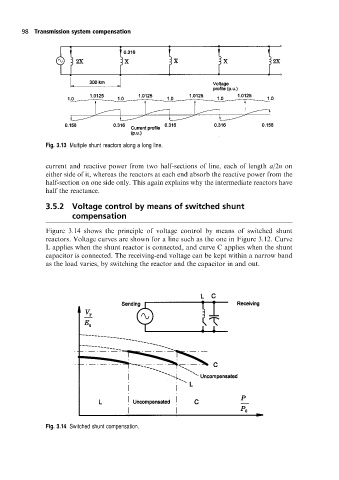
3.5.2 Voltage control by means of switched shunt
compensation
Figure 3.14 shows the principle of voltage control by means of switched shunt
reactors. Voltage curves are shown for a line such as the one in Figure 3.12. Curve
L applies when the shunt reactor is connected, and curve C applies when the shunt
capacitor is connected. The receiving-end voltage can be kept within a narrow band
as the load varies, by switching the reactor and the capacitor in and out.
Fig. 3.14 Switched shunt compensation.