
Page 114 - Power Electronic Control in Electrical Systems
P. 114
//SYS21/F:/PEC/REVISES_10-11-01/075065126-CH003.3D ± 102 ± [82±105/24] 17.11.2001 9:53AM
102 Transmission system compensation
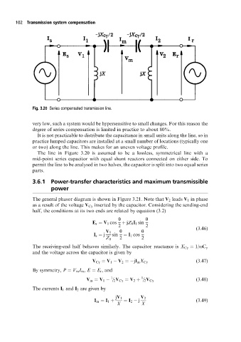
Fig. 3.20 Series compensated transmission line.
very low, such a system would be hypersensitive to small changes. For this reason the
degree of series compensation is limited in practice to about 80%.
It is not practicable to distribute the capacitance in small units along the line, so in
practice lumped capacitors are installed at a small number of locations (typically one
or two) along the line. This makes for an uneven voltage profile.
The line in Figure 3.20 is assumed to be a lossless, symmetrical line with a
mid-point series capacitor with equal shunt reactors connected on either side. To
permit the line to be analysed in two halves, the capacitor is split into two equal series
parts.
3.6.1 Power-transfer characteristics and maximum transmissible
power
The general phasor diagram is shown in Figure 3.21. Note that V 2 leads V 1 in phase
as a result of the voltage V Cg inserted by the capacitor. Considering the sending-end
half, the conditions at its two ends are related by equation (3.2)
y y
E s V 1 cos jZ 0 I 1 sin
2 2 (3:46)
V 1 y y
I s j sin I 1 cos
Z 0 2 2
The receiving-end half behaves similarly. The capacitor reactance is X Cg 1/oC g
and the voltage across the capacitor is given by
V Cg V 1 V 2 jI m X Cg (3:47)
By symmetry, P V m I m , E E r , and
1 1
V m V 1 = 2 V Cg V 2 = 2 V Cg (3:48)
The currents I 1 and I 2 are given by
jV 1 V 2
I m I 1 I 2 j (3:49)
X X