Page 112 - Power Electronic Control in Electrical Systems
P. 112

//SYS21/F:/PEC/REVISES_10-11-01/075065126-CH003.3D ± 100 ± [82±105/24] 17.11.2001 9:53AM


               100 Transmission system compensation


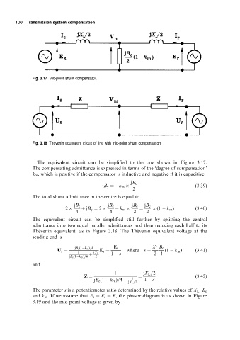
                      Fig. 3.17 Mid-point shunt compensator.


                              Â
                      Fig. 3.18 Thevenin equivalent circuit of line with mid-point shunt compensation.


                        The equivalent circuit can be simplified to the one shown in Figure 3.17.
                      The compensating admittance is expressed in terms of the `degree of compensation'
                      k m , which is positive if the compensator is inductive and negative if it is capacitive
                                                              jB c
                                                  jB g ˆ k m                            (3:39)
                                                               2
                      The total shunt admittance in the centre is equal to

                                       jB c         jB c      jB c  jB c
                                   2      ‡ jB g ˆ 2      k m    ˆ       (1   k m )     (3:40)
                                       4             4         2    2
                      The equivalent circuit can be simplified still further by splitting the central
                      admittance into two equal parallel admittances and then reducing each half to its
                      The  venin equivalent, as in Figure 3.18. The The  venin equivalent voltage at the
                      sending end is
                                          1
                                       jB c (1 k m )=4  E s            X L B c
                                U s ˆ            E s ˆ      where  s ˆ      (1   k m )  (3:41)
                                        1      jX L   1   s            2 4
                                     jB c (1 k m )=4  ‡  2
                      and
                                                       1           jX L =2
                                           Z ˆ                1  ˆ                      (3:42)
                                               jB c (1   k m )=4 ‡  1   s
                                                             jX L =2
                      The parameter s is a potentiometer ratio determined by the relative values of X L , B c
                      and k m . If we assume that E s ˆ E r ˆ E, the phasor diagram is as shown in Figure
                      3.19 and the mid-point voltage is given by
   107   108   109   110   111   112   113   114   115   116   117