
Page 111 - Power Electronic Control in Electrical Systems
P. 111
//SYS21/F:/PEC/REVISES_10-11-01/075065126-CH003.3D ± 99 ± [82±105/24] 17.11.2001 9:53AM
Power electronic control in electrical systems 99
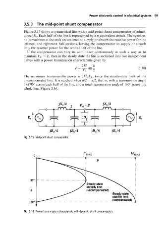
3.5.3 The mid-point shunt compensator
Figure 3.15 shows a symmetrical line with a mid-point shunt compensator of admit-
tance jB g . Each half of the line is represented by a p-equivalent circuit. The synchro-
nous machines at the ends are assumed to supply or absorb the reactive power for the
leftmost and rightmost half-sections, leaving the compensator to supply or absorb
only the reactive power for the central half of the line.
If the compensator can vary its admittance continuously in such a way as to
maintain V m E, then in the steady state the line is sectioned into two independent
halves with a power transmission characteristic given by
2E 2 d
P sin (3:38)
X L 2
2
The maximum transmissible power is 2E /X L , twice the steady-state limit of the
uncompensated line. It is reached when d/2 p/2, that is, with a transmission angle
d of 90 across each half of the line, and a total transmission angle of 180 across the
whole line, Figure 3.16.
Fig. 3.15 Mid-point shunt compensator.
Fig. 3.16 Power transmission characteristic with dynamic shunt compensation.