
Page 101 - Power Electronic Control in Electrical Systems
P. 101
//SYS21/F:/PEC/REVISES_10-11-01/075065126-CH003.3D ± 89 ± [82±105/24] 17.11.2001 9:53AM
Power electronic control in electrical systems 89
sudden open-circuiting of the line at the receiving end, the sending-end voltage tends
to rise immediately to the open-circuit voltage of the sending-end generators, which
exceeds the terminal voltage by approximately the voltage drop due to the prior
current flowing in their short-circuit reactances.
3.3 Uncompensated lines under load
3.3.1 Radial line with fixed sending-end voltage
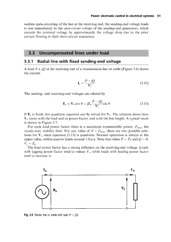
A load P jQ at the receiving end of a transmission line or cable (Figure 3.6) draws
the current
P jQ
I r (3:12)
V r
The sending- and receiving-end voltages are related by
P jQ
E s V r cos y jZ 0 sin y (3:13)
V r
If E s is fixed, this quadratic equation can be solved for V r . The solution shows how
V r varies with the load and its power factor, and with the line length. A typical result
is shown in Figure 3.7.
For each load power factor there is a maximum transmissible power, P max , the
steady-state stability limit. For any value of P < P max , there are two possible solu-
tions for V r , since equation (3.13) is quadratic. Normal operation is always at the
upper value, within narrow limits around 1.0 p.u. Note that when P P 0 and Q 0,
V r E s .
The load power factor has a strong influence on the receiving-end voltage. Loads
with lagging power factor tend to reduce V r , while loads with leading power factor
tend to increase it.
Fig. 3.6 Radial line or cable with load P jQ.