
Page 125 - Power Electronic Control in Electrical Systems
P. 125
//SYS21/F:/PEC/REVISES_10-11-01/075065126-CH004.3D ± 113 ± [106±152/47] 17.11.2001 9:54AM
Power electronic control in electrical systems 113
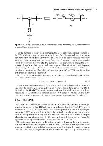
Fig. 4.5 DVR. (a) VSC connected to the AC networkvia a series transformer; and (b) series connected
variable solid state voltage source.
For the purpose of steady state operation, the DVR performs a similar function to
the SPS; it injects voltage in quadrature with one of the line end voltages in order to
regulate active power flow. However, the DVR is a far more versatile controller
because it does not draw reactive power from the AC system; it has its own reactive
power provisions in the form of a DC capacitor. This characteristic makes the DVR
capable of regulating both active and reactive power flow within the limits imposed
by its rating. It may perform the role of a phase shifter and a variable series
impedance compensator. The schematic representation of the DVR and its equiva-
lent circuit are shown in Figure 4.5.
The DVR power flow model presented in this chapter is based on the concept of a
series connected voltage source
V cR jV cR j(cos y cR j sin y cR ) (4:8)
The magnitude and phase angle of the DVR model are adjusted using Newton's
algorithm to satisfy a specified active and reactive power flow across the DVR.
Similarly to the STATCOM, maximum and minimum limits will exist for the voltage
magnitude jV cR j, which are a function of the DVR capacitor rating. On the other
hand, the voltage phase angle y cR can take any value between 0 and 2p radians.
4.2.6 The UPFC
The UPFC may be seen to consist of one STATCOM and one DVR sharing a
common capacitor on their DC side and a unified control system. The UPFC allows
simultaneous control of active power flow, reactive power flow and voltage magni-
tude at the UPFC terminals. Alternatively, the controller may be set to control one or
more of these parameters in any combination or to control none of them. A simpler
schematic representation of the UPFC shown in Figure 1.12 is given in Figure 4.6
together with its equivalent circuit (Fuerte-Esquivel et al., 2000).
The active power demanded by the series converter is drawn by the shunt converter
from the AC network and supplied via the DC link. The inverted voltage of the series
converter is added to the nodal voltage, at say node l, to boost the nodal voltage at
node m. The voltage magnitude of the inverted voltage jV cR j provides voltage