
Page 204 - Power Electronic Control in Electrical Systems
P. 204
//SYS21/F:/PEC/REVISES_10-11-01/075065126-CH006.3D ± 192 ± [177±262/86] 17.11.2001 10:22AM
192 Power electronic equipment
In the absence of other circuit elements, we must also specify that the capacitor be
precharged to the voltage V C0 ^ v, that is, it must hold the prior charge ^ v/C. This
is because any prior DC voltage on the capacitor cannot be accounted for in the
simple circuit of Figure 6.16. In practice this voltage would appear distributed across
series inductance and resistance with a portion across the thyristor switch.
With these restrictions, that is, dv/dt 0 and V C0 ^ v at t 0, we have the ideal
case of transient-free switching, as illustrated in Figure 6.15. This concept is the basis
for switching control in the TSC. In principle, once each capacitor is charged to either
the positive or the negative system peak voltage, it is possible to switch any or all of
the capacitors on or off for any integral number of half-cycles without transients.
6.2.5.2 Switching transients in the general case
Under practical conditions, it is necessary to consider inductance and resistance.
First consider the addition of series inductance in Figure 6.16. In any practical TSC
circuit, there must always be at least enough series inductance to keep di/dt within the
capability of the thyristors. In some circuits there may be more than this minimum
inductance. In the following, resistance will be neglected because it is generally small
and its omission makes no significant difference to the calculation of the first few
peaks of voltage and current.
The presence of inductance and capacitance together makes the transients oscilla-
tory. The natural frequency of the transients will be shown to be a key factor in the
magnitudes of the voltages and currents after switching, yet it is not entirely under
the designer's control because the total series inductance includes the supply-system
inductance which, if known at all, may be known only approximately. It also includes
the inductance of the step-down transformer (if used), which is subject to other
constraints and cannot be chosen freely.
It may not always be possible to connect the capacitor at a crest value of the supply
voltage. It is necessary to ask what other events in the supply-voltage cycle can be
detected and used to initiate the gating of the thyristors, and what will be the
resulting transients.
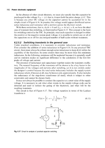
The circuit is that of Figure 6.17. The voltage equation in terms of the Laplace
transform is
1 V C0
V(s) L s I(s) (6:11)
C s s
Fig. 6.17 Circuit for analysis of practical capacitor switching.