Page 203 - Power Electronic Control in Electrical Systems
P. 203

//SYS21/F:/PEC/REVISES_10-11-01/075065126-CH006.3D ± 191 ± [177±262/86] 17.11.2001 10:22AM


                                                            Power electronic control in electrical systems 191


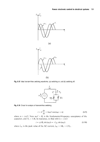
                      Fig. 6.15 Ideal transient-free switching waveforms. (a) switching on; and (b) switching off.


                      Fig. 6.16 Circuit for analysis of transient-free switching.

                                                  dv
                                             i ˆ C   ˆ ^ vo 0 C cos (o 0 t ‡ a)           (6:9)
                                                   dt
                      where a ˆ p/2. Now o 0 C ˆ B c is the fundamental-frequency susceptance of the
                      capacitor, and X c ˆ 1/B c its reactance, so that with a ˆ p/2
                                                               ^
                                            i ˆ ^ vB c sin (o 0 t) ˆ‡i AC sin (o 0 t)    (6:10)
                                                              ^
                            ^
                      where i AC is the peak value of the AC current, i AC ˆ ^ vB C ˆ ^ v/X C .
   198   199   200   201   202   203   204   205   206   207   208