
Page 202 - Power Electronic Control in Electrical Systems
P. 202
//SYS21/F:/PEC/REVISES_10-11-01/075065126-CH006.3D ± 190 ± [177±262/86] 17.11.2001 10:22AM
190 Power electronic equipment
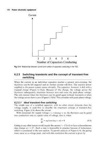
Fig. 6.14 Relationship between current and number of capacitors conducting in the TSC.
6.2.5 Switching transients and the concept of transient-free
switching
When the current in an individual capacitor reaches a natural zero-crossing, the
thyristors can be left ungated and no further current will flow. The reactive power
supplied to the power system ceases abruptly. The capacitor, however, is left with a
trapped charge (Figure 6.15(a)). Because of this charge, the voltage across the
thyristors subsequently alternates between zero and twice the peak-phase voltage.
The only instant when the thyristors can be gated again without transients is when
the voltage across them is zero (Figure 6.15(b)). This coincides with peak-phase voltage.
6.2.5.1 Ideal transient-free switching
The simple case of a switched capacitor, with no other circuit elements than the
voltage supply, is used first to describe the important concept of transient-free
switching. Figure 6.16 shows the circuit.
With sinusoidal AC supply voltage v ^ v sin (o 0 t a), the thyristors can be gated
into conduction only at a peak value of voltage, that is, when
dv
o 0 ^ v cos (o 0 t a) 0 (6:8)
dt
Gating at any other instant would require the current i Cdv/dt to have a discontinuous
step change at t 0 . Such a step is impossible in practice because of inductance,
which is considered in the next section. To permit analysis of Figure 6.16, the gating
must occur at a voltage peak, and with this restriction the current is given by