Page 205 - Power Electronic Control in Electrical Systems
P. 205

//SYS21/F:/PEC/REVISES_10-11-01/075065126-CH006.3D ± 193 ± [177±262/86] 17.11.2001 10:22AM


                                                            Power electronic control in electrical systems 193

                      The supply voltage is given by v ˆ ^ v sin (o 0 t ‡ a). Time is measured from the first
                      instant when a thyristor is gated, corresponding to the angle a on the voltage wave-
                      form. By straightforward transform manipulation and inverse transformation we get
                      the instantaneous current expressed as
                                                         n 2
                             ^                                               ^
                        i(t) ˆ i AC cos (o 0 t ‡ a)   nB C V C0    ^ v sin a sin (o n t)   i AC cos a cos (o n t)
                                                         2
                                                        n   1
                                                                                         (6:12)
                      where o n is the natural frequency of the circuit
                                                         1
                                                  o n ˆ p  ˆ no o                 (6:13)
                                                         LC
                      and
                                                          r 
                                                            X C
                                                      n ˆ                                (6:14)
                                                            X L
                      n is the per-unit natural frequency.
                        The current has a fundamental-frequency component i AC which leads the supply
                                                      ^
                      voltage by p/2 radians. Its amplitude i AC is given by
                                                              n 2
                                                   ^
                                                   i AC ˆ ^ vB C                         (6:15)
                                                             2
                                                            n   1
                      and is naturally proportional to the fundamental-frequency susceptance of the
                                                                    2
                                                                 2
                                                                                       2
                                                                                    2
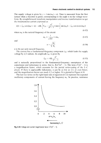
                      capacitance and inductance in series, that is, B c n /(n   1). The term n /(n   1) is
                      a magnification factor, which accounts for the partial series-tuning of the L±C
                      circuit. If there is appreciable inductance, n can be as low as 2.5, or even lower,
                      and the magnification factor can reach 1.2 or higher. It is plotted in Figure 6.18.
                        The last two terms on the right-hand side of equation (6.12) represent the expected
                      oscillatory components of current having the frequency o n . In practice, resistance


                                                         2
                                                            2
                      Fig. 6.18 Voltage and current magnification factor n /(n   1).
   200   201   202   203   204   205   206   207   208   209   210