
Page 199 - Power Electronic Control in Electrical Systems
P. 199
//SYS21/F:/PEC/REVISES_10-11-01/075065126-CH006.3D ± 187 ± [177±262/86] 17.11.2001 10:22AM
Power electronic control in electrical systems 187
breaker. The groups can be tuned to particular frequencies by small series reactors in
each phase, to filter the harmonic currents generated by the TCR and so prevent
them from flowing in the external system. One possible choice is to have groups
tuned to the 5th and 7th harmonics, with another arranged as a high-pass filter. The
capacitors arranged as filters, and indeed the entire compensator, must be designed
with careful attention to their effect on the resonances of the power system at the
point of connection.
It is common for the compensation requirement to extend into both the lagging
and the leading ranges. A TCR with fixed capacitors cannot have a lagging current
unless the TCR reactive power rating exceeds that of the capacitors. The net reactive
power absorption rating with the capacitors connected equals the difference between
the ratings of the TCR and the capacitors. In such cases the required TCR rating can
be very large indeed (up to some hundreds of MVAr in transmission system appli-
cations). When the net reactive power is small or lagging, large reactive current
circulates between the TCR and the capacitors without performing any useful func-
tion in the power system. For this reason the capacitors are sometimes designed to be
switched in groups, so that the degree of capacitive bias in the voltage/current
characteristic can be adjusted in steps. If this is done, a smaller `interpolating' TCR
can be used.
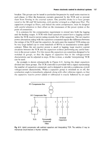
An example is shown schematically in Figure 6.11, having the shunt capacitors
divided into three groups. The TCR controller is provided with a signal representing
the number of capacitors connected, and is designed to provide a continuous overall
voltage/current characteristic. When a capacitor group is switched on or off, the
conduction angle is immediately adjusted, along with other reference signals, so that
the capacitive reactive power added or subtracted is exactly balanced by an equal
Fig. 6.11 Hybrid compensator with switched capacitors and `interpolating' TCR. The switches S may be
mechanical circuit breakers or thyristor switches.