
Page 196 - Power Electronic Control in Electrical Systems
P. 196
//SYS21/F:/PEC/REVISES_10-11-01/075065126-CH006.3D ± 184 ± [177±262/86] 17.11.2001 10:22AM
184 Power electronic equipment
Fig. 6.7 TCR with more than 180 of conduction in each leg to reduce harmonic currents.
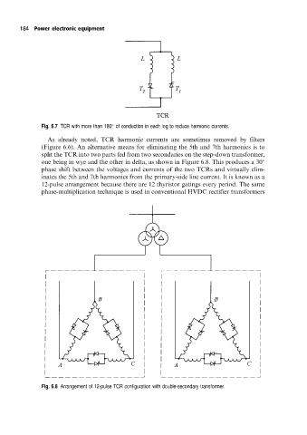
As already noted, TCR harmonic currents are sometimes removed by filters
(Figure 6.6). An alternative means for eliminating the 5th and 7th harmonics is to
split the TCR into two parts fed from two secondaries on the step-down transformer,
one being in wye and the other in delta, as shown in Figure 6.8. This produces a 30
phase shift between the voltages and currents of the two TCRs and virtually elim-
inates the 5th and 7th harmonics from the primary-side line current. It is known as a
12-pulse arrangement because there are 12 thyristor gatings every period. The same
phase-multiplication technique is used in conventional HVDC rectifier transformers
Fig. 6.8 Arrangement of 12-pulse TCR configuration with double-secondary transformer.