
Page 194 - Power Electronic Control in Electrical Systems
P. 194
//SYS21/F:/PEC/REVISES_10-11-01/075065126-CH006.3D ± 182 ± [177±262/86] 17.11.2001 10:22AM
182 Power electronic equipment
6.2.1.3 Harmonics
Increasing the gating angle (reducing the conduction angle) has two other important
effects. First, the power losses decrease in both the thyristor controller and the
reactor. Second, the current waveform becomes less sinusoidal; in other words, the
TCR generates harmonic currents. If the gating angles are balanced, (i.e. equal for
both thyristors), all odd order harmonics are generated, and the rms value of the nth
harmonic component is given by
4 V sin (n 1)a sin (n 1)a sin na
I n cos a n 3, 5, 7 ... (6:7)
p X L 2(n 1 2(n 1) n
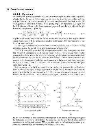
Figure 6.5(a) shows the variation of the amplitudes of some of the major (lower-
order) harmonics with the conduction angles, and Figure 6.5(b) the variation of the
total harmonic content.
Table 6.2 gives the maximum amplitudes of the harmonics down to the 37th. (Note
that the maxima do not all occur at the same conduction angle.)
The TCR described so far is only a single-phase device. For three-phase systems
the preferred arrangement is shown in Figure 6.6; i.e. three single-phase TCRs
connected in delta. When the system is balanced, all the triplen harmonics circulate
in the closed delta and are absent from the line currents. All the other harmonics are
present in the line currents and their amplitudes are in the same proportions as shown
in Figure 6.5 and Table 6.2. However, the waveforms differ from those ones pre-
sented in Figure 6.2.
It is important in the TCR to ensure that the conduction angles of the two back-to-
back thyristors are equal. Unequal conduction angles would produce even harmonic
components in the current, including DC. They would also cause unequal thermal
stresses in the thyristors. The requirement for equal conduction also limits s to a
5
4 1.0
% 3 5th
2 0.8 Fundamental
1
0 p.u.
3 0.6
2
% 7th
1
0 0.4
2 Total of
% 1 11th Harmonics
0 0.2
1
% 13th
0
0 20 40 60 80 100 120 140 160 180 0 180
σ
σ
Conduction Angle , deg. Conduction Angle , deg.
(a) (b)
Fig. 6.5 TCR Harmonics. (a) major harmonic current components of TCR. Each is shown as a percentage of
the fundamental component at full conduction. The percentages are the same for both phase and line
currents; and (b) total harmonic content of TCR current, as a fraction of the fundamental component at full
conduction. The percentages are the same for both phase and line currents.