
Page 192 - Power Electronic Control in Electrical Systems
P. 192
//SYS21/F:/PEC/REVISES_10-11-01/075065126-CH006.3D ± 180 ± [177±262/86] 17.11.2001 10:22AM
180 Power electronic equipment
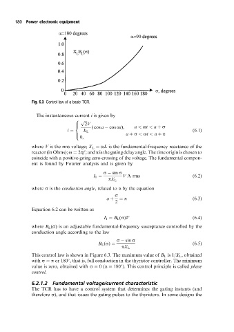
Fig. 6.3 Control law of a basic TCR.
The instantaneous current i is given by
p
8
2V
( cos a cos ot),
>
< a < ot < a s
i X L (6:1)
a s < ot < a p
>
0,
:
where V is the rms voltage; X L oL is the fundamental-frequency reactance of the
reactor (in Ohms); o 2pf ; and a is the gating delay angle. The time origin is chosen to
coincide with a positive-going zero-crossing of the voltage. The fundamental compon-
ent is found by Fourier analysis and is given by
s sin s
I 1 V A rms (6:2)
pX L
where s is the conduction angle, related to a by the equation
s
a p (6:3)
2
Equation 6.2 can be written as
I 1 B L (s)V (6:4)
where B L (s) is an adjustable fundamental-frequency susceptance controlled by the
conduction angle according to the law
s sin s
B L (s) (6:5)
pX L
This control law is shown in Figure 6.3. The maximum value of B L is 1/X L , obtained
with s p or 180 , that is, full conduction in the thyristor controller. The minimum
value is zero, obtained with s 0(a 180 ). This control principle is called phase
control.
6.2.1.2 Fundamental voltage/current characteristic
The TCR has to have a control system that determines the gating instants (and
therefore s), and that issues the gating pulses to the thyristors. In some designs the