
Page 197 - Power Electronic Control in Electrical Systems
P. 197
//SYS21/F:/PEC/REVISES_10-11-01/075065126-CH006.3D ± 185 ± [177±262/86] 17.11.2001 10:22AM
Power electronic control in electrical systems 185
for harmonic cancellation. With the 12-pulse scheme, the lowest-order characteristic
harmonics are the 11th and 13th. It can be used without filters for the 5th and 7th
harmonics, which is an advantage when system resonances occur near these frequen-
cies. For higher-order harmonics a plain capacitor is often sufficient, connected on
the low-voltage side of the step-down transformer. Otherwise a high-pass filter may
be used. The generation of third-harmonic currents under unbalanced conditions is
similar to that in the six-pulse arrangement (Figure 6.6).
With both 6-pulse and 12-pulse TCR compensators, the need for filters and their
frequency responses must be evaluated with due regard to the possibility of unbal-
anced operation. The influence of other capacitor banks and sources of harmonic
currents in the electrical neighbourhood of the compensator must also be taken into
account. For this purpose, several software packages are available and some
examples with a specific one will be provided in Chapter 8.
The 12-pulse connection has the further advantage that if one half is faulted the
other may be able to continue to operate normally. The control system must take into
account the 30 phase shift between the two TCRs, and must be designed to ensure
accurate harmonic cancellation. A variant of the 12-pulse TCR uses two separate
transformers instead of one with two secondaries.
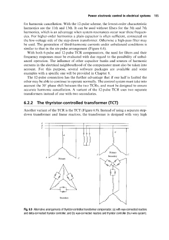
6.2.2 The thyristor-controlled transformer (TCT)
Another variant of the TCR is the TCT (Figure 6.9). Instead of using a separate step-
down transformer and linear reactors, the transformer is designed with very high
Fig. 6.9 Alternative arrangements of thyristor-controlled transformer compensator. (a) with wye-connected reactors
and delta-connected thyristor controller; and (b) wye-connected reactors and thyristor controller (four-wire system).