
Page 193 - Power Electronic Control in Electrical Systems
P. 193
//SYS21/F:/PEC/REVISES_10-11-01/075065126-CH006.3D ± 181 ± [177±262/86] 17.11.2001 10:22AM
Power electronic control in electrical systems 181
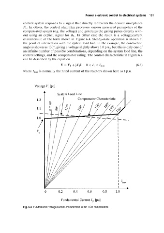
control system responds to a signal that directly represents the desired susceptance
B L . In others, the control algorithm processes various measured parameters of the
compensated system (e.g. the voltage) and generates the gating pulses directly with-
out using an explicit signal for B L . In either case the result is a voltage/current
characteristic of the form shown in Figure 6.4. Steady-state operation is shown at
the point of intersection with the system load line. In the example, the conduction
angle is shown as 130 , giving a voltage slightly above 1.0 p.u., but this is only one of
an infinite number of possible combinations, depending on the system load line, the
control settings, and the compensator rating. The control characteristic in Figure 6.4
can be described by the equation
V V k jX S I 1 0 < I 1 < I max (6:6)
where I max is normally the rated current of the reactors shown here as 1 p.u.
Fig. 6.4 Fundamental voltage/current characteristic in the TCR compensator.