
Page 198 - Power Electronic Control in Electrical Systems
P. 198
//SYS21/F:/PEC/REVISES_10-11-01/075065126-CH006.3D ± 186 ± [177±262/86] 17.11.2001 10:22AM
186 Power electronic equipment
leakage reactance, and the secondary windings are merely short-circuited through the
thyristor controllers. A gapped core is necessary to obtain the high leakage reactance,
and the transformer can take the form of three single-phase transformers. With the
arrangements in Figure 6.9 there is no secondary bus and any shunt capacitors must
be connected at the primary voltage unless a separate step-down transformer is
provided. The high leakage reactance helps protect the transformer against short-
circuit forces during secondary faults. Because of its linearity and large thermal mass
the TCT can usefully withstand overloads in the lagging (absorbing) regime.
6.2.3The TCR with shunt capacitors
It is important to note that the TCR current (the compensating current) can be varied
continuously, without steps, between zero and a maximum value corresponding to full
conduction. The current is always lagging, so that reactive power can only be
absorbed. However, the TCR compensator can be biased by shunt capacitors so
that its overall power factor is leading and reactive power is generated into the
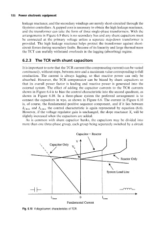
external system. The effect of adding the capacitor currents to the TCR currents
shown in Figure 6.4 is to bias the control characteristic into the second quadrant, as
shown in Figure 6.10. In a three-phase system the preferred arrangement is to
connect the capacitors in wye, as shown in Figure 6.6. The current in Figure 6.10
is, of course, the fundamental positive sequence component, and if it lies between
I C max and I L max the control characteristic is again represented by equation (6.6).
However, if the voltage regulator gain is unchanged, the slope reactance X s will be
slightly increased when the capacitors are added.
As is common with shunt capacitor banks, the capacitors may be divided into
more than one three-phase group, each group being separately switched by a circuit
Fig. 6.10 Voltage/current characteristics of TCR.