
Page 245 - Power Electronic Control in Electrical Systems
P. 245
//SYS21/F:/PEC/REVISES_10-11-01/075065126-CH006.3D ± 233 ± [177±262/86] 17.11.2001 10:23AM
Power electronic control in electrical systems 233
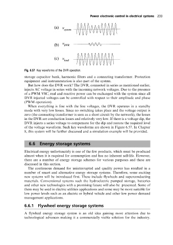
Fig. 6.57 Key waveforms of the DVR operation.
storage capacitor bank, harmonic filters and a connecting transformer. Protection
equipment and instrumentation is also part of the system.
But how does the DVR work? The DVR, connected in series as mentioned earlier,
injects AC voltage in series with the incoming network voltages. Due to the presence
of a PWM VSC, real and reactive power can be exchanged with the system since all
DVR injected voltages can be controlled with respect to their amplitude and phase
(PWM operation).
When everything is fine with the line voltages, the DVR operates in a standby
mode with very low losses. Since no switching takes place and the voltage output is
zero (the connecting transformer is seen as a short circuit by the network), the losses
in the DVR are conduction losses and relatively very low. If there is a voltage dip, the
DVR injects a series voltage to compensate for the dip and restore the required level
of the voltage waveform. Such key waveforms are shown in Figure 6.57. In Chapter
8, this system will be further discussed and a simulation example will be provided.
6.6 Energy storage systems
Electrical energy unfortunately is one of the few products, which must be produced
almost when it is required for consumption and has no inherent self-life. However,
there are a number of energy storage schemes for various purposes and these are
discussed in this section.
The continuous demand for uninterrupted and quality power has resulted in a
number of smart and alternative energy storage systems. Therefore, some exciting
new systems will be introduced first. These include flywheels and superconducting
materials. Conventional systems such the hydroelectric pumped storage, batteries
and other new technologies with a promising future will also be presented. Some of
them may be used in electric utilities applications and some may be more suitable for
low power levels such as an electric or hybrid vehicle and other low power demand
management applications.
6.6.1 Flywheel energy storage systems
A flywheel energy storage system is an old idea gaining more attention due to
technological advances making it a commercially viable solution for the industry.