
Page 246 - Power Electronic Control in Electrical Systems
P. 246
//SYS21/F:/PEC/REVISES_10-11-01/075065126-CH006.3D ± 234 ± [177±262/86] 17.11.2001 10:23AM
234 Power electronic equipment
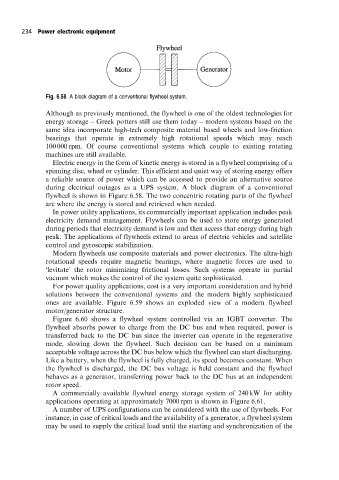
Fig. 6.58 A block diagram of a conventional flywheel system.
Although as previously mentioned, the flywheel is one of the oldest technologies for
energy storage ± Greek potters still use them today ± modern systems based on the
same idea incorporate high-tech composite material based wheels and low-friction
bearings that operate in extremely high rotational speeds which may reach
100 000 rpm. Of course conventional systems which couple to existing rotating
machines are still available.
Electric energy in the form of kinetic energy is stored in a flywheel comprising of a
spinning disc, wheel or cylinder. This efficient and quiet way of storing energy offers
a reliable source of power which can be accessed to provide an alternative source
during electrical outages as a UPS system. A block diagram of a conventional
flywheel is shown in Figure 6.58. The two concentric rotating parts of the flywheel
are where the energy is stored and retrieved when needed.
In power utility applications, its commercially important application includes peak
electricity demand management. Flywheels can be used to store energy generated
during periods that electricity demand is low and then access that energy during high
peak. The applications of flywheels extend to areas of electric vehicles and satellite
control and gyroscopic stabilization.
Modern flywheels use composite materials and power electronics. The ultra-high
rotational speeds require magnetic bearings, where magnetic forces are used to
`levitate' the rotor minimizing frictional losses. Such systems operate in partial
vacuum which makes the control of the system quite sophisticated.
For power quality applications, cost is a very important consideration and hybrid
solutions between the conventional systems and the modern highly sophisticated
ones are available. Figure 6.59 shows an exploded view of a modern flywheel
motor/generator structure.
Figure 6.60 shows a flywheel system controlled via an IGBT converter. The
flywheel absorbs power to charge from the DC bus and when required, power is
transferred back to the DC bus since the inverter can operate in the regenerative
mode, slowing down the flywheel. Such decision can be based on a minimum
acceptable voltage across the DC bus below which the flywheel can start discharging.
Like a battery, when the flywheel is fully charged, its speed becomes constant. When
the flywheel is discharged, the DC bus voltage is held constant and the flywheel
behaves as a generator, transferring power back to the DC bus at an independent
rotor speed.
A commercially available flywheel energy storage system of 240 kW for utility
applications operating at approximately 7000 rpm is shown in Figure 6.61.
A number of UPS configurations can be considered with the use of flywheels. For
instance, in case of critical loads and the availability of a generator, a flywheel system
may be used to supply the critical load until the starting and synchronization of the