
Page 241 - Power Electronic Control in Electrical Systems
P. 241
//SYS21/F:/PEC/REVISES_10-11-01/075065126-CH006.3D ± 229 ± [177±262/86] 17.11.2001 10:23AM
Power electronic control in electrical systems 229
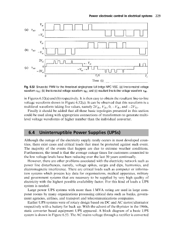
Fig. 6.52 Sinusoidal PWM for the three-level single-phase full bridge NPC VSC. (a) line-to-neutral voltage
waveform v AO ; (b) line-to-neutral voltage waveform v BO ; and (c) resultant line-to-line voltage waveform v AB .
in Figures 6.52(a) and (b) respectively. It is then easy to obtain the resultant line-to-line
voltage waveform shown in Figure 6.52(c). It can be observed that this waveform is a
multilevel waveform taking five values, namely 2V dc , V dc ,0, V dc ,and 2V dc .
Finally it should be added that all these basic topologies presented in this section
could be used along with appropriate connections of transformers to generate multi-
level voltage waveforms of higher number than the individual converter.
6.4 Uninterruptible Power Supplies (UPSs)
Although the outage of the electricity supply rarely occurs in most developed coun-
tries, there exist cases and critical loads that must be protected against such event.
The majority of the events that happen are due to extreme weather conditions.
Furthermore, the trend is that the average outage times for customers connected to
the low voltage levels have been reducing over the last 50 years continually.
However, there are other problems associated with the electricity network such as
power line disturbances, namely, voltage spikes, surges and dips, harmonics, and
electromagnetic interference. There are critical loads such as computer or informa-
tion systems which process key data for organizations, medical apparatus, military
and government systems that are necessary to be supplied by very high quality of
electricity with the highest possible availability factor. For this kind of loads a UPS
system is needed.
Large power UPS systems with more than 1 MVA rating are used in large com-
puter rooms by many organizations processing critical data such as banks, govern-
ment agencies, airlines, and transport and telecommunications companies.
Earlier UPS systems were of rotary design based on DC and AC motor/alternator
respectively with a battery for back up. With the advent of the thyristor in the 1960s,
static converter based equipment UPS appeared. A block diagram of a basic UPS
system is shown in Figure 6.53. The AC mains voltage through a rectifier is converted