
Page 237 - Power Electronic Control in Electrical Systems
P. 237
//SYS21/F:/PEC/REVISES_10-11-01/075065126-CH006.3D ± 225 ± [177±262/86] 17.11.2001 10:23AM
Power electronic control in electrical systems 225
only difference is that the output voltage v o is taken across points A and B in this
case. Therefore, the two-levels of the output waveform take V dc and V dc values.
The control method for the single-phase full-bridge VSC assumes that the switches
(S 1 , S 4 ) and (S 2 , S 3 ) are treated as pairs and obviously in a complementary manner
(Figure 6.26). The normalized amplitude values of the fundamental and the various
harmonics are identical as confirmed with the Figure 6.48(c).
In a previous section, two control methods were presented for a single-phase full-
bridge VSC, namely the square-wave method and the phase-shifted square-wave
method. The second control method can be extended to include PWM methods.
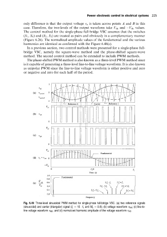
The phase-shifted PWM method is also known as a three-level PWM method since
is it capable of generating a three-level line-to-line voltage waveform. It is also known
as unipolar PWM since the line-to-line voltage waveform is either positive and zero
or negative and zero for each half of the period.
Fig. 6.49 Three-level sinusoidal PWM method for single-phase full-bridge VSC. (a) two reference signals
(sinusoidal) and carrier (triangular) signal (f c 15 f 1 and M a 0:8); (b) voltage waveform v AN ; (c) line-to-
line voltage waveform v AB ; and (d) normalized harmonic amplitude of the voltage waveform v AB .