
Page 239 - Power Electronic Control in Electrical Systems
P. 239
//SYS21/F:/PEC/REVISES_10-11-01/075065126-CH006.3D ± 227 ± [177±262/86] 17.11.2001 10:23AM
Power electronic control in electrical systems 227
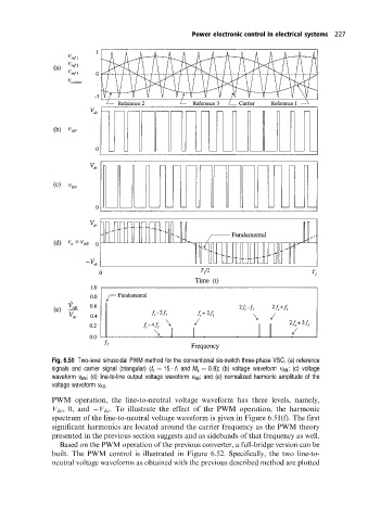
Fig. 6.50 Two-level sinusoidal PWM method for the conventional six-switch three-phase VSC. (a) reference
signals and carrier signal (triangular) (f c 15 f 1 and M a 0:8); (b) voltage waveform v AN ; (c) voltage
waveform v BN ; (d) line-to-line output voltage waveform v AB ; and (e) normalized harmonic amplitude of the
voltage waveform v AB .
PWM operation, the line-to-neutral voltage waveform has three levels, namely,
V dc , 0, and V dc . To illustrate the effect of the PWM operation, the harmonic
spectrum of the line-to-neutral voltage waveform is given in Figure 6.51(f). The first
significant harmonics are located around the carrier frequency as the PWM theory
presented in the previous section suggests and as sidebands of that frequency as well.
Based on the PWM operation of the previous converter, a full-bridge version can be
built. The PWM control is illustrated in Figure 6.52. Specifically, the two line-to-
neutral voltage waveforms as obtained with the previous described method are plotted