
Page 234 - Power Electronic Control in Electrical Systems
P. 234
//SYS21/F:/PEC/REVISES_10-11-01/075065126-CH006.3D ± 222 ± [177±262/86] 17.11.2001 10:23AM
222 Power electronic equipment
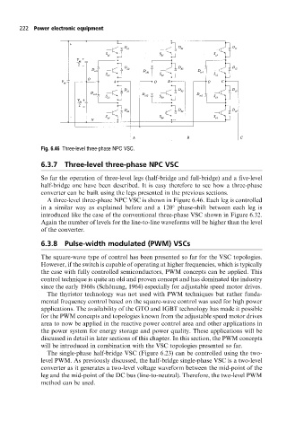
Fig. 6.46 Three-level three-phase NPC VSC.
6.3.7 Three-level three-phase NPC VSC
So far the operation of three-level legs (half-bridge and full-bridge) and a five-level
half-bridge one have been described. It is easy therefore to see how a three-phase
converter can be built using the legs presented in the previous sections.
A three-level three-phase NPC VSC is shown in Figure 6.46. Each leg is controlled
in a similar way as explained before and a 120 phase-shift between each leg is
introduced like the case of the conventional three-phase VSC shown in Figure 6.32.
Again the number of levels for the line-to-line waveforms will be higher than the level
of the converter.
6.3.8 Pulse-width modulated (PWM) VSCs
The square-wave type of control has been presented so far for the VSC topologies.
However, if the switch is capable of operating at higher frequencies, which is typically
the case with fully controlled semiconductors, PWM concepts can be applied. This
control technique is quite an old and proven concept and has dominated the industry
since the early 1960s (Scho È nung, 1964) especially for adjustable speed motor drives.
The thyristor technology was not used with PWM techniques but rather funda-
mental frequency control based on the square-wave control was used for high power
applications. The availability of the GTO and IGBT technology has made it possible
for the PWM concepts and topologies known from the adjustable speed motor drives
area to now be applied in the reactive power control area and other applications in
the power system for energy storage and power quality. These applications will be
discussed in detail in later sections of this chapter. In this section, the PWM concepts
will be introduced in combination with the VSC topologies presented so far.
The single-phase half-bridge VSC (Figure 6.23) can be controlled using the two-
level PWM. As previously discussed, the half-bridge single-phase VSC is a two-level
converter as it generates a two-level voltage waveform between the mid-point of the
leg and the mid-point of the DC bus (line-to-neutral). Therefore, the two-level PWM
method can be used.