
Page 232 - Power Electronic Control in Electrical Systems
P. 232
//SYS21/F:/PEC/REVISES_10-11-01/075065126-CH006.3D ± 220 ± [177±262/86] 17.11.2001 10:23AM
220 Power electronic equipment
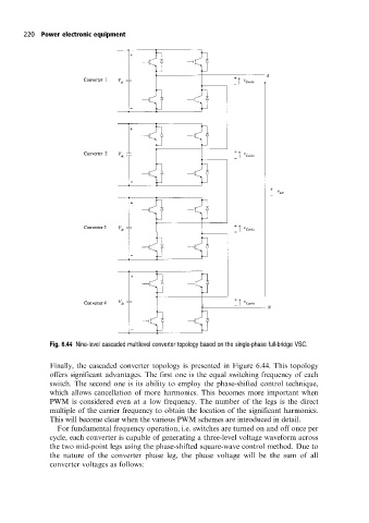
Fig. 6.44 Nine-level cascaded multilevel converter topology based on the single-phase full-bridge VSC.
Finally, the cascaded converter topology is presented in Figure 6.44. This topology
offers significant advantages. The first one is the equal switching frequency of each
switch. The second one is its ability to employ the phase-shifted control technique,
which allows cancellation of more harmonics. This becomes more important when
PWM is considered even at a low frequency. The number of the legs is the direct
multiple of the carrier frequency to obtain the location of the significant harmonics.
This will become clear when the various PWM schemes are introduced in detail.
For fundamental frequency operation, i.e. switches are turned on and off once per
cycle, each converter is capable of generating a three-level voltage waveform across
the two mid-point legs using the phase-shifted square-wave control method. Due to
the nature of the converter phase leg, the phase voltage will be the sum of all
converter voltages as follows: