
Page 230 - Power Electronic Control in Electrical Systems
P. 230
//SYS21/F:/PEC/REVISES_10-11-01/075065126-CH006.3D ± 218 ± [177±262/86] 17.11.2001 10:23AM
218 Power electronic equipment
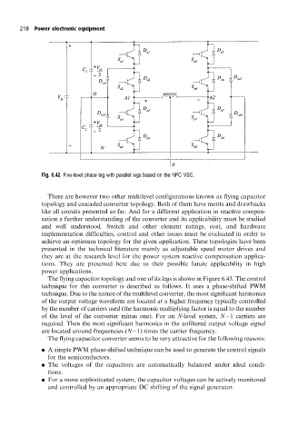
Fig. 6.42 Five-level phase leg with parallel legs based on the NPC VSC.
There are however two other multilevel configurations known as flying capacitor
topology and cascaded converter topology. Both of them have merits and drawbacks
like all circuits presented so far. And for a different application in reactive compen-
sation a further understanding of the converter and its applicability must be studied
and well understood. Switch and other element ratings, cost, and hardware
implementation difficulties, control and other issues must be evaluated in order to
achieve an optimum topology for the given application. These topologies have been
presented in the technical literature mainly as adjustable speed motor drives and
they are at the research level for the power system reactive compensation applica-
tions. They are presented here due to their possible future applicability in high
power applications.
The flying capacitor topology and one of its legs is shown in Figure 6.43. The control
technique for this converter is described as follows. It uses a phase-shifted PWM
technique. Due to the nature of the multilevel converter, the most significant harmonics
of the output voltage waveform are located at a higher frequency typically controlled
by the number of carriers used (the harmonic multiplying factor is equal to the number
of the level of the converter minus one). For an N-level system, N 1 carriers are
required. Then the most significant harmonics in the unfiltered output voltage signal
are located around frequencies (N 1) times the carrier frequency.
The flying capacitor converter seems to be very attractive for the following reasons:
. A simple PWM phase-shifted technique can be used to generate the control signals
for the semiconductors.
. The voltages of the capacitors are automatically balanced under ideal condi-
tions.
. For a more sophisticated system, the capacitor voltages can be actively monitored
and controlled by an appropriate DC shifting of the signal generator.