
Page 233 - Power Electronic Control in Electrical Systems
P. 233
//SYS21/F:/PEC/REVISES_10-11-01/075065126-CH006.3D ± 221 ± [177±262/86] 17.11.2001 10:23AM
Power electronic control in electrical systems 221
(6:31)
v AN v con1a v con2a v con3a v con4a
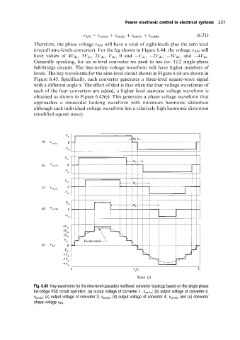
Therefore, the phase voltage v AN will have a total of eight-levels plus the zero level
(overall nine-levels converter). For the leg shown in Figure 6.44, the voltage v AN will
have values of 4V dc ,3V dc ,2V dc , V dc , 0 and V dc , 2V dc , 3V dc ,and 4V dc .
Generally speaking, for an m-level converter we need to use (m 1)/2 single-phase
full-bridge circuits. The line-to-line voltage waveform will have higher numbers of
levels. The key waveforms for the nine-level circuit shown in Figure 6.44 are shown in
Figure 6.45. Specifically, each converter generates a three-level square-wave signal
with a different angle a. The effect of that is that when the four voltage waveforms of
each of the four converters are added, a higher level staircase voltage waveform is
obtained as shown in Figure 6.45(e). This generates a phase voltage waveform that
approaches a sinusoidal looking waveform with minimum harmonic distortion
although each individual voltage waveform has a relatively high harmonic distortion
(modified square wave).
Fig. 6.45 Key waveforms for the nine-level cascaded multilevel converter topology based on the single-phase
full-bridge VSC circuit operation. (a) output voltage of converter 1, v con1a ; (b) output voltage of converter 2,
v con2a ; (c) output voltage of converter 3, v con3a ; (d) output voltage of converter 4, v con4a ; and (e) converter
phase voltage v AN .