
Page 236 - Power Electronic Control in Electrical Systems
P. 236
//SYS21/F:/PEC/REVISES_10-11-01/075065126-CH006.3D ± 224 ± [177±262/86] 17.11.2001 10:23AM
224 Power electronic equipment
where
^
A s is the amplitude of the sinusoidal signal and
^
A c is the amplitude of the triangular signal.
The PWM method shown in Figure 6.47 is presented for an amplitude modulation
^
^
ratio of 0.8 (A s 0:8p:u:, A c 1p:u:). When the harmonic content of the resultant
voltage waveform is considered, the following observations can be made. The wave-
form v AO contains a fundamental component with amplitude equal to M a on a per
unit basis as shown in Figure 6.47(c). The harmonics are positioned as sidebands as
follows
f h k f c m f 1 (6:33)
where
k 1, 3, 5, ... when m 0, 2, 4, 6, ...
and
k 2, 4, 6, ... when m 1, 3, 5, ...
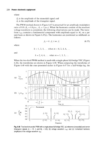
When the two-level PWM method is used with a single-phase full-bridge VSC (Figure
6.26), the waveforms are shown in Figure 6.48. When comparing the waveforms of
Figure 6.48 with the ones presented earlier in Figure 6.47 for a half-bridge leg, the
Fig. 6.48 Two-level sinusoidal PWM with a single-phase full-bridge VSC. (a) reference (sinusoidal) and carrier
(triangular) signals (f c 15 f 1 and M a 0:8); (b) voltage waveform AB ; and (c) normalized harmonic
amplitude of the voltage waveform v AB .