
Page 235 - Power Electronic Control in Electrical Systems
P. 235
//SYS21/F:/PEC/REVISES_10-11-01/075065126-CH006.3D ± 223 ± [177±262/86] 17.11.2001 10:23AM
Power electronic control in electrical systems 223
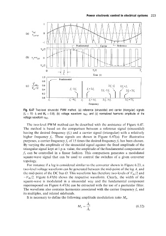
Fig. 6.47 Two-level sinusoidal PWM method. (a) reference (sinusoidal) and carrier (triangular) signals
(f c 15 f 1 and M a 0:8); (b) voltage waveform v AO ; and (c) normalized harmonic amplitude of the
voltage waveform v AO .
The two-level PWM method can be described with the assistance of Figure 6.47.
The method is based on the comparison between a reference signal (sinusoidal)
having the desired frequency (f 1 ) and a carrier signal (triangular) with a relatively
higher frequency f c . These signals are shown in Figure 6.47(a). For illustrative
purposes, a carrier frequency f c of 15 times the desired frequency f 1 has been chosen.
By varying the amplitude of the sinusoidal signal against the fixed amplitude of the
triangular signal kept at 1 p.u. value, the amplitude of the fundamental component at
f 1 can be controlled in a linear fashion. This comparison generates a modulated
square-wave signal that can be used to control the switches of a given converter
topology.
For instance if a leg is considered similar to the converter shown in Figure 6.23, a
two-level voltage waveform can be generated between the mid-point of the leg A, and
the mid-point of the DC bus O. This waveform has therefore two-levels of V dc /2 and
V dc /2. Figure 6.47(b) shows the respective waveform. Clearly, the width of the
square-wave is modulated in a sinusoidal way and the fundamental component
superimposed on Figure 6.47(b) can be extracted with the use of a particular filter.
The waveform also contains harmonics associated with the carrier frequency f c and
its multiples, and related sidebands.
It is necessary to define the following amplitude modulation ratio M a .
^
A s
M a (6:32)
^
A c