
Page 229 - Power Electronic Control in Electrical Systems
P. 229
//SYS21/F:/PEC/REVISES_10-11-01/075065126-CH006.3D ± 217 ± [177±262/86] 17.11.2001 10:23AM
Power electronic control in electrical systems 217
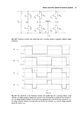
Fig. 6.40 Three-level converter with parallel legs and a summing inductor to generate multilevel voltage
waveforms.
Fig. 6.41 Key waveforms of the three-level converter with parallel legs and a summing inductor circuit
operation. (a) voltage waveform between the mid-point of the left phase leg A 1 and the DC bus mid-point O,
v A10 ; (b) voltage waveform between the mid-point of the right phase leg A 2 and the DC bus mid-point O, v A20 ;
(c) voltage waveform between the phase point and the DC bus mid-point, v AO ; and (d) voltage waveform
across the inductor v A1A2 .