
Page 224 - Power Electronic Control in Electrical Systems
P. 224
//SYS21/F:/PEC/REVISES_10-11-01/075065126-CH006.3D ± 212 ± [177±262/86] 17.11.2001 10:23AM
212 Power electronic equipment
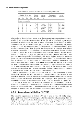
Table 6.5 Modes of operation of the three-level half-bridge NPC VSC
Switching device state Output Output Conducting Power
voltage current semiconductor transfer
S a1 S a2 S a3 S a4 v o v AO i o
Square-wave method
1 1 0 0 V dc /2 Positive S a1 S a2 DC ! AC
1 1 0 0 V dc /2 Negative D a1 D a2 AC ! DC
0 0 1 1 V dc /2 Negative S a3 S a4 DC ! AC
0 0 1 1 V dc /2 Positive D a3 D a4 AC ! DC
0 1 1 0 0 Positive S a2 D ca1 None
0 1 1 0 0 Negative S a3 D ca2 None
when switches S a1 and S a2 are turned on at the same time, the voltage of the capacitor
C 1 (V dc /2) will be applied across the load. When this pair of switches is turned on, the
other pair of switches (S a3 , S a4 ) must be turned off to avoid destruction of the bridge.
Similarly when the switches S a3 and S a4 are turned on simultaneously the output
voltage v o v AO becomes negative ( V dc /2) due to the voltage of capacitor C 2 being
applied across the load. Now, in order for the converter to generate zero voltage
across the output (the third level of the output voltage waveform), the two switches
S a2 and S a3 are turned on simultaneously and the other two switches S a1 and S a4 are
turned off. This way, through the assistance of the two clamping diodes D ca1 and
D ca2 , the potential of the DC bus mid-point O is across the load generating zero volts
in the voltage waveform v AO as shown in Figure 6.35(a). The control signals for the
four switches S a1 , S a2 , S a3 , and S a4 are plotted in Figures 6.35(b)±(e) respectively. It is
clear that the switches S a1 and S a3 have complementary signals, and the same applies
for the control signals between the switches S a4 and S a2 . The duration that the switch
S a1 is on simultaneously with S a2 controls the length of the output voltage that is
positive as explained earlier. The same applies for the interval that the output voltage
is negative when the switch S a4 is on simultaneously with S a3 .
Table 6.5 summarizes the modes of operation of the three-level single-phase half-
bridge VSC based on the NPC topology with clamping diodes. This converter is also
capable of operating in all four quadrants, since both the output voltage and current can
be both positive and negative (bidirectional VSC topology). These quadrants of opera-
tion of the three-level single-phase half-bridge NPC VSC are indicated in Figure 6.36.
It should be noted that the waveform generated by the three-level converter
(Figure 6.35(a)) and the single-phase full-bridge VSC with the phase-shifted method
(Figure 6.29(a)) are identical. Therefore the harmonic content is also identical as
analysed in Section 6.3.2 and plotted in a normalized form in Figure 6.31.
6.3.5 Single-phase full-bridge NPC VSC
The converter leg presented in Section 6.3.4 can be used to build full-bridge single-
phase and three-phase VSC topologies with the capability of generating three or
higher-level voltage waveforms. In this case, the line-to-line voltage waveform will be
of a higher than three level. However, the converter in the technical literature is called
a three-level one since the number of levels of the line-to-line voltage waveform is not