
Page 222 - Power Electronic Control in Electrical Systems
P. 222
//SYS21/F:/PEC/REVISES_10-11-01/075065126-CH006.3D ± 210 ± [177±262/86] 17.11.2001 10:23AM
210 Power electronic equipment
The normalized spectrum of the line-to-DC bus mid-point and the line-to-line
voltage waveforms are plotted in Figures 6.33(f) and (g) respectively. It can be seen
that the voltage waveforms v AO , v BO , and v CO contain all odd harmonics. The load
connection as shown in Figure 6.32 does not allow 3rd harmonic and all multiples to
flow, and this is confirmed with the spectrum of the line-to-line voltage waveform v AB
where 3rd, 9th and 15th harmonics are eliminated as shown in Figure 6.33(g).
6.3.4 Single-phase half-bridge neutral-point-clamped (NPC)
VSC
For single-phase applications, so far the half-bridge and the full-bridge conventional
topologies have been discussed in detail. These converters have the capability to
generate two-level voltage waveforms in both cases where only frequency control is
possible and a separate control of the DC bus voltage must be employed to control
the output AC voltage waveform (when square-wave control method is considered).
Except of course for the case where a phase-shifted control method is used for the
single-phase full-bridge VSC topology. In this case, the converter is capable of
generating a three-level waveform and with controlled amplitude.
However, there exists a topology that is capable of generating a three-level voltage
waveform at the output with a half-bridge version. Such a converter leg has made a
significant contribution in the general area of converters, as a building block,
especially for high power applications. We present this VSC topology in this section.
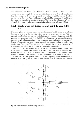
A three-level half-bridge VSC based on the NPC topology is shown in Figure 6.34
(Nabae et al., 1981). In this version the neutral point is clamped with diodes.
Fig. 6.34 Three-level single-phase half-bridge NPC VSC.