
Page 218 - Power Electronic Control in Electrical Systems
P. 218
//SYS21/F:/PEC/REVISES_10-11-01/075065126-CH006.3D ± 206 ± [177±262/86] 17.11.2001 10:23AM
206 Power electronic equipment
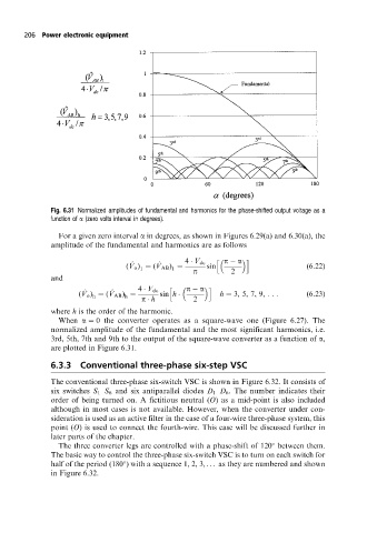
Fig. 6.31 Normalized amplitudes of fundamental and harmonics for the phase-shifted output voltage as a
function of a (zero volts interval in degrees).
For a given zero interval a in degrees, as shown in Figures 6.29(a) and 6.30(a), the
amplitude of the fundamental and harmonics are as follows
h p a i
^ ^ 4 V dc
(V o ) (V AB ) p sin 2 (6:22)
1
1
and
^ ^ 4 V dc h p a i
(V o ) (V AB ) sin h h 3, 5, 7, 9, ::: (6:23)
h
h
p h 2
where h is the order of the harmonic.
When a 0 the converter operates as a square-wave one (Figure 6.27). The
normalized amplitude of the fundamental and the most significant harmonics, i.e.
3rd, 5th, 7th and 9th to the output of the square-wave converter as a function of a,
are plotted in Figure 6.31.
6.3.3 Conventional three-phase six-step VSC
The conventional three-phase six-switch VSC is shown in Figure 6.32. It consists of
six switches S 1 ±S 6 and six antiparallel diodes D 1 ±D 6 . The number indicates their
order of being turned on. A fictitious neutral (O) as a mid-point is also included
although in most cases is not available. However, when the converter under con-
sideration is used as an active filter in the case of a four-wire three-phase system, this
point (O) is used to connect the fourth-wire. This case will be discussed further in
later parts of the chapter.
The three converter legs are controlled with a phase-shift of 120 between them.
The basic way to control the three-phase six-switch VSC is to turn on each switch for
half of the period (180 ) with a sequence 1, 2, 3, . . . as they are numbered and shown
in Figure 6.32.