
Page 214 - Power Electronic Control in Electrical Systems
P. 214
//SYS21/F:/PEC/REVISES_10-11-01/075065126-CH006.3D ± 202 ± [177±262/86] 17.11.2001 10:22AM
202 Power electronic equipment
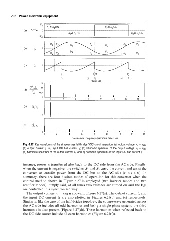
Fig. 6.27 Key waveforms of the single-phase full-bridge VSC circuit operation. (a) output voltage v o v AB ;
(b) output current i o ; (c) input DC bus current i d ; (d) harmonic spectrum of the output voltage v o v AB ;
(e) harmonic spectrum of the output current i o ; and (f) harmonic spectrum of the input DC bus current i d .
instance, power is transferred also back to the DC side from the AC side. Finally,
when the current is negative, the switches S 2 and S 3 carry the current and assist the
converter to transfer power from the DC bus to the AC side (t 2 < t < t 3 ). In
summary, there are four distinct modes of operation for this converter when the
control method shown in Figure 6.27 is employed (two inverter modes and two
rectifier modes). Simply said, at all times two switches are turned on and the legs
are controlled in a synchronized way.
The output voltage v o v AB is shown in Figure 6.27(a). The output current i o and
the input DC current i d are also plotted in Figures 6.27(b) and (c) respectively.
Similarly, like the case of the half-bridge topology, the square-wave generated across
the AC side includes all odd harmonics and being a single-phase system, the third
harmonic is also present (Figure 6.27(d)). These harmonics when reflected back to
the DC side source include all even harmonics (Figure 6.27(f)).